1. Scope
The DN ranges includes DN15mm~600mm(1/2”~24”) and PN ranges from PN1.6MPa~20MPa(ANSI CLASS150~1500) threaded, flanged, BW and SW swing and lifting check valve.
2.Usage:
2.1 This valve is to prevent medium flows backwards in pipe system.
2.2 Valve material is selected according to medium。
2.2.1WCB valve is suitable for water, steam and oil medium etc.
2.2.2SS valve is suitable for corrosion medium.
2.3Temperature:
2.3.1Common WCB is suitable for temperature -29℃ ~+425℃
2.3.2Alloy valve is suitable for temperature≤550℃
2.3.3SS valve is suitable for temperature-196℃ ~+200℃
3. Structure and performance characteristics
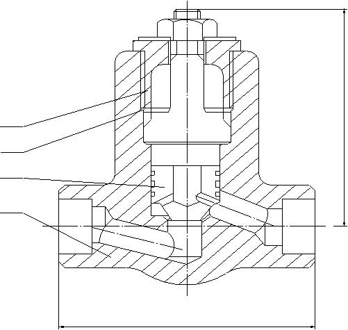
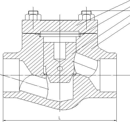
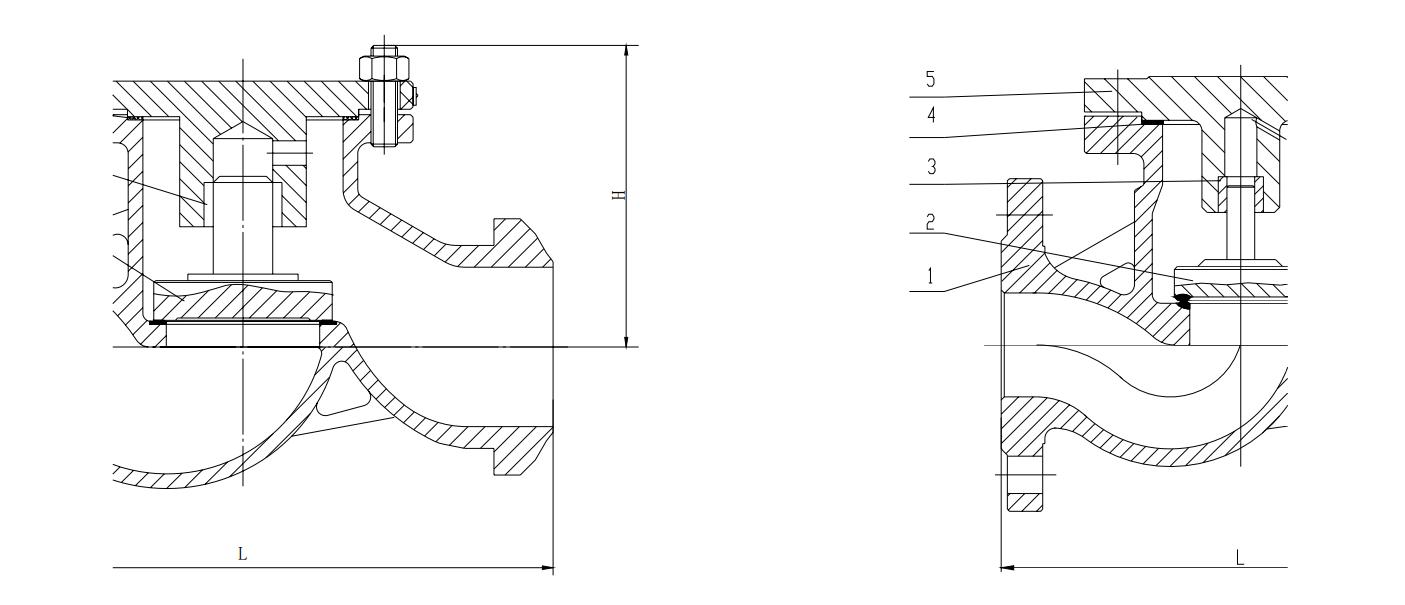
3.1 Basic structure is as below:
3.2 PTFE and flexible graphite is adopted for damageable gasket to ensure sealing performance.

(A)Welding forged high pressure self-sealing lifting check valve

(B)Welding forged lifting check valve
1.body 2. disc 3. gasket 4. bonnet

(C) BW Lifting Check Valve
(D) Flanged Check Valve
1.Body 2. Disc 3. Shaft 4. Gasket 5. Bonnet

(E)BW Swing Check Valve

(F) Flanged Swing Check
1.Body 2. Seat 3. Disc 4. Rocker Arm 5. Pin Shaft 6. Yoke 7. Gasket 8. Bonnet
3.3 Main Components Material
| Name | Material | Name | Material |
| Body | Carbon Steel, SS, Alloy Steel | Pin Shaft | SS, Cr13 |
| Seat Seal | Surfacing13Cr, STL, Rubber | Yoke | Carbon Steel, SS, Alloy Steel |
| Disc | Carbon Steel, SS, Alloy Steel | Gasket | PTFE, Flexible Graphite |
| Rocker Arm | Carbon Steel, SS, Alloy Steel | Bonnet | Carbon Steel, SS, Alloy Steel |
3.4 Performance Chart
| Rating | Strength test (MPa) | Seal test (MPa) | Air seal test (MPa) |
| Class150 | 3.0 | 2.2 | 0.4~0.7 |
| Class300 | 7.7 | 5.7 | 0.4~0.7 |
| Class600 | 15.3 | 11.3 | 0.4~0.7 |
| Class900 | 23.0 | 17.0 | 0.4~0.7 |
| Class1500 | 38.4 | 28.2 | 0.4~0.7 |
| Rating | Strength test (MPa) | Seal test (MPa) | Air seal test (MPa) |
| 16 | 2.4 | 1.76 | 0.4~0.7 |
| 25 | 3.75 | 2.75 | 0.4~0.7 |
| 40 | 6.0 | 4.4 | 0.4~0.7 |
| 64 | 9.6 | 7.04 | 0.4~0.7 |
| 100 | 15.0 | 11.0 | 0.4~0.7 |
| 160 | 24.0 | 17.6 | 0.4~0.7 |
| 200 | 30.0 | 22.0 | 0.4~0.7 |
4. Work theory
Check valve automatically opens and closes the disc to prevent medium flows backwards by the medium flow.
5. Applicable valve standards but not limited to:
(1)API 6D-2002 (2)ASME B16.5-2003
(3)ASME B16.10-2000 (4)API 598-2004
(5)GB/T 12235-1989 (6)GB/T 12236-1989
(7)GB/T 9113.1-2000 (8)GB/T 12221-2005 (9)GB/T 13927-1992
6. Storage & Maintenance & Installation & Operation
6.1 The valve should be stored in dry and well ventilated room .the passage ends should be plugged with covers.
6.2 Valves under long-time storage should be examined and cleaned regularly, especially seating face to prevent damage of it, and the seating face should be coated with rust inhibiting oil .
6.3 Valve marking should be checked to comply with usage.
6.4 Valve cavity and sealing surface should be checked before installation and remove the dirt if there is any.
6.5Arrow direction should be same as the flow direction.
6.6 Lifting vertical disc check valve should be installed vertically to the pipeline. Lifting horizontal disc check valve should be installed horizontally to the pipeline.
6.7 The vibration should be checked and pipeline medium pressure change should be noted to prevent water effect.
7.Possible problems, causes and remedial measure
| Possible Problems | Causes | Remedial Measure |
| Disc cannot open or close |
|
|
| Leakage |
|
|
| Noise and Vibration |
|
8. Warranty
After the valve is put into use, the warranty period of valve is 12 months, but does not exceed 18 months after delivery date. During warranty period, the manufacturer will provide repair service or spare parts free of charge for the damage due to material, workmanship or damage provided that operation is correct.
Post time: May-19-2022

